
Welding Safety: Wire Feeder Power Cables – Secure, Sized, and Single-Length (WeldSafe Essentials 9)
Loose connections and undersized cables on wire feeders are a fast track to overheating, burned terminals, voltage drops, and even fires. In WeldSafe Essentials 9, we focus on the often-ignored wire feeder power cable (the control/motor cable from the welding power source to the feeder). Proper tightening, correct conductor sizing based on current and length, and using one continuous cable are essential for safety, performance, and equipment longevity.
Why Wire Feeder Power Cables Matter
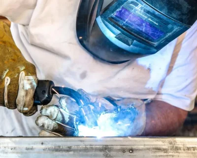
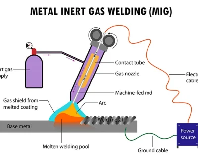
The wire feeder motor draws significant current, especially during high-duty-cycle MIG or flux-cored welding. Problems from poor cable management include:
- Loose terminals → High resistance → Heat buildup → Melted lugs, burned insulation, fire risk
- Undersized conductors → Excessive voltage drop → Weak motor torque, inconsistent wire feeding, bird-nesting
- Spliced cables → Additional resistance points and mechanical weakness → Premature failure
A burned terminal can shut down production for hours and cost hundreds in repairs—preventable with basic diligence.
Critical Rules for Wire Feeder Power Cables
1. Tighten Connections Securely
- Always torque output terminals on the power source and feeder plugs to manufacturer specifications (usually 10–15 Nm).
- Inspect before every shift: look for discoloration, melting, or looseness.
- Clean contact surfaces—oxidation increases resistance.
2. Size the Cable Correctly
Conductor cross-section (mm²) must match the welder’s rated output current and total cable length. Use the table below as a minimum guideline (based on typical manufacturer recommendations for 4-conductor control/power cables at ≤40°C ambient).
| Welder Rated | Cable Length | ||
|---|---|---|---|
| Current | 15–45 m | 45–60 m | 60–70 m |
| 200 A | 35 mm² | 50 mm² | 70 mm² |
| 250 A | 50 mm² | 70 mm² | 95 mm² |
| 300 A | 70 mm² | 95 mm² | 105 mm² |
| 350 A | 95 mm² | 105 mm² | 105 mm² |
| 500 A | 105 mm² | 105 mm² | 105 mm² |
Larger cross-sections reduce voltage drop and heat. When in doubt, go one size up.

3. Use One Continuous Cable – No Splicing
- Never join short cables end-to-end with connectors or tape.
- Splices create extra resistance, corrosion points, and mechanical stress.
- Always order or cut a single-length cable that reaches from power source to feeder position.
Quick Installation Checklist
- Terminals clean and torqued to spec
- Cable cross-section meets or exceeds table for your current & length
- Single continuous length – no splices or extensions
- Cable routed away from sharp edges, heat, and traffic
- Strain relief and support clamps in place (prevent pulling on terminals)
Pro Tips for Longevity
- Use genuine manufacturer cables—they’re designed for the exact voltage, current, and control signals.
- Coil excess cable loosely—tight bends damage strands.
- In dusty or wet environments, choose cables with extra abrasion/moisture-resistant jackets.

Tight, Thick, and Whole
A secure, properly sized, single-length wire feeder power cable eliminates overheating, ensures smooth wire feeding, and protects your investment. Take two minutes to check terminals and sizing—it beats replacing a melted feeder plug on a deadline.
Ever seen a burned feeder terminal? Share the story (and the lesson) below.