What Is a 3-in-1 H Beam Machine and How It Works
Introduction
The H beam is one of the most widely used structural components in steel construction — from industrial facility frameworks to bridge girders. How efficiently and accurately H beams are produced directly determines the delivery timeline and cost structure of any steel fabrication operation.
The 3-in-1 H beam machine addresses a long-standing efficiency bottleneck in traditional separate-machine configurations. Yet most descriptions of this equipment stay at the functional level, rarely explaining the underlying process logic or mechanical structure in depth. This article breaks down how a 3-in-1 machine actually works — covering process principles, mechanical components, and automation configurations — to give both procurement decision-makers and technical engineers a clearer foundation for equipment evaluation.
The Three Process Stages and Their Technical Logic
The Assembly Stage: Automatic Positioning and Clamping
An H beam consists of one web plate and two flange plates. The assembly stage positions and clamps all three plates accurately before welding begins.
In traditional manual or semi-automatic assembly, operators mark reference lines, position the plates by hand, and tack-weld them in place. This is time-consuming and relies heavily on operator skill — positional errors at this stage carry forward and affect the dimensional accuracy of the finished beam.
The assembly mechanism on a 3-in-1 machine uses hydraulic or servo-driven automatic clamping:
- The web plate feeds in vertically while both flange plates are simultaneously clamped from either side
- Hydraulic pressure is applied automatically — no manual tack welding required
- Clamping force and positioning accuracy are controlled through parameter settings, delivering consistent repeatability
The core value of this mechanism is the elimination of manual positioning error, providing a stable geometric foundation for the welding stage that follows.
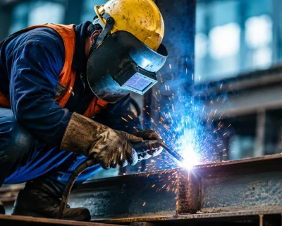
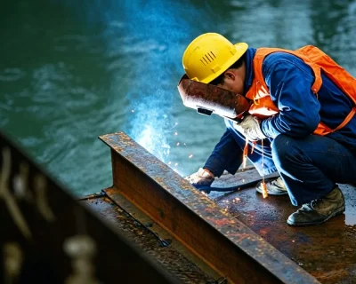
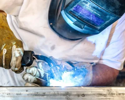
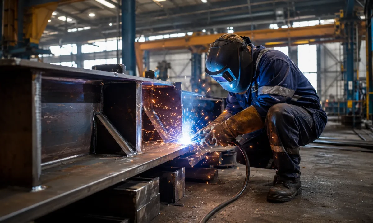
The Welding Stage: Simultaneous Double-Sided Submerged Arc Welding
Once assembly is complete, the welding mechanism performs continuous fillet welds along the joints between the web plate and both flange plates. 3-in-1 machines typically use submerged arc welding (SAW) for several reasons:
- The welding arc burns beneath a layer of flux, producing minimal spatter and consistent, clean weld profiles
- Higher current settings are achievable, supporting full-penetration welding on medium-to-thick plate
- Stable welding speed suits the continuous long straight welds required in H beam production
In a double-sided simultaneous welding configuration, two welding heads operate on both sides of the web plate at the same time. Compared to single-side sequential welding, this produces more balanced heat input, reduces welding distortion, and improves production throughput.
The Straightening Stage: Hot-State Pressure Correction
After welding, thermal stress causes the flange plates to tilt inward — a deformation known as angular distortion. The straightening stage restores the flanges to the perpendicular angle required by design specifications.
The straightening mechanism on a 3-in-1 machine is positioned immediately after the welding station, taking advantage of the hot straightening window:
- Steel that has just been welded retains elevated temperature, reducing its yield strength below the cold-state value
- Applying correction force at this stage requires significantly less pressure and produces more uniform results
- Straightening rolls apply lateral pressure to the flange plates, bringing angular deformation back within tolerance
Straightening roll pressure, angle, and stroke are all adjustable via parameter settings to accommodate different H beam cross-section sizes.
Mechanical Structure and Components
Frame and Guide Rail System
The main frame of a 3-in-1 machine is a welded steel structure that serves as the load-bearing foundation for all functional modules. Longitudinal guide rails run the length of the machine, along which workpieces advance at a controlled feed rate. The three functional modules — assembly, welding, and straightening — are arranged in sequence along the same axis.
Guide rail precision directly determines the straightness of finished beams. Rail deviation during production causes lateral bowing in the H beam, so high-quality machines use precision-machined and calibrated rail systems.
Feed and Drive System
Workpiece advancement through the machine is handled by a drive roll system:
- Powered drive rolls driven by electric motors provide the forward feed force
- Passive support rolls carry the workpiece weight and reduce deflection under load
- Drive speed is adjustable to match the welding travel speed required for different workpiece specifications
In fully automatic configurations, feed speed is linked to welding parameters — the system automatically maintains the optimal welding travel speed without operator adjustment.
Welding Heads and Flux Recovery System
The submerged arc welding heads are the core of the welding module, comprising:
- Wire reels and wire feed mechanisms
- Flux hoppers and flux recovery units
- Welding power sources and control wiring
The flux recovery system collects unfused flux and recirculates it, reducing consumable costs and keeping the welding zone clear. Double-sided configurations run two complete welding head assemblies simultaneously, requiring coordinated power supply capacity and control system integration.
Straightening Roll Assembly
The straightening module is built around a set of hydraulically driven correction rolls:
- Horizontal rolls provide vertical support for the workpiece
- Lateral straightening rolls apply sideward pressure to the flange plates
- The hydraulic system delivers adjustable correction force to accommodate different plate thicknesses and deformation magnitudes
Roll material and hardness directly affect service life. In high-volume production environments, straightening rolls are among the primary wear components requiring periodic replacement.
Control System
Modern 3-in-1 machines are equipped with PLC or CNC control systems offering:
- Parameter storage: welding current, travel speed, and straightening pressure settings for different beam specifications can be preset and recalled
- Fault diagnostics: sensors monitor all mechanism status in real time, triggering automatic alarms on abnormal conditions
- Operator interface: touchscreen operation reduces dependence on high operator skill levels
Higher automation configurations include more complete control system functionality — from parameter recall through to production record logging and digital quality management.
Automation Configuration Levels
3-in-1 machines on the market vary significantly in automation level. Three broad tiers are common:
Semi-Automatic Configuration
- Assembly requires manual operator assistance for positioning
- Welding parameters set manually; machine executes the welding sequence
- Straightening pressure adjusted manually
- Best suited to: smaller production scales, frequently changing beam specifications, or operations with budget constraints
Fully Automatic Configuration
- Assembly clamping is fully automatic with no operator intervention required
- Welding parameters recalled automatically from preset programs
- Straightening pressure matched automatically to the beam specification
- Best suited to: operations with concentrated beam specifications, higher production volumes, and a priority on consistent cycle time
Fully Automatic CNC Configuration
- Adds CNC numerical control capability on top of full automation
- Supports precise control of complex cross-section parameters
- Production data logged in real time, supporting quality traceability
- Best suited to: large-scale steel fabrication bases with strict dimensional tolerance requirements and quality management system needs
Matching the Machine to Your Operation
Different factory profiles prioritize different aspects of the 3-in-1 configuration:
New production line planning: When building a line from the ground up, the 3-in-1 configuration delivers its most comprehensive advantages in floor space, labor, and cycle time. It is the recommended starting point for new facility planning.
Upgrading from existing separate equipment: Factories with existing assembly and welding machines should evaluate the remaining value of current equipment before deciding whether to replace everything with an integrated system or phase in straightening capability first as an interim step.
Concentrated beam specification mix: The more consistent the beam specifications being produced, the greater the efficiency gains from full automation. Low changeover frequency allows automated parameter recall to deliver its full throughput benefit.
Varied beam specification mix: Frequent specification changes demand flexibility in changeover. When evaluating equipment for high-variety production, prioritize changeover time and the ease of parameter adjustment over raw throughput figures.
Conclusion
The value of a 3-in-1 H beam machine goes beyond the physical consolidation of three machines into one footprint. It lies in the thermal continuity between process stages and the systemic efficiency gains that come from integrated automatic control. Understanding the working principles and mechanical structure of this equipment enables more precise evaluation during selection — not just comparing specification sheets, but assessing whether the machine genuinely fits the production context it will operate in.
If you are planning an H beam production line or evaluating an equipment upgrade, contact the ZMDE technical team for specification recommendations tailored to your actual production requirements.