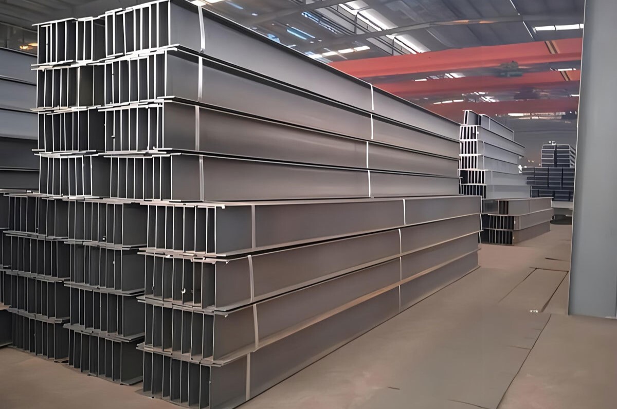
XUZ12-0 U-Beam Assembly Machine User Manual
Overview
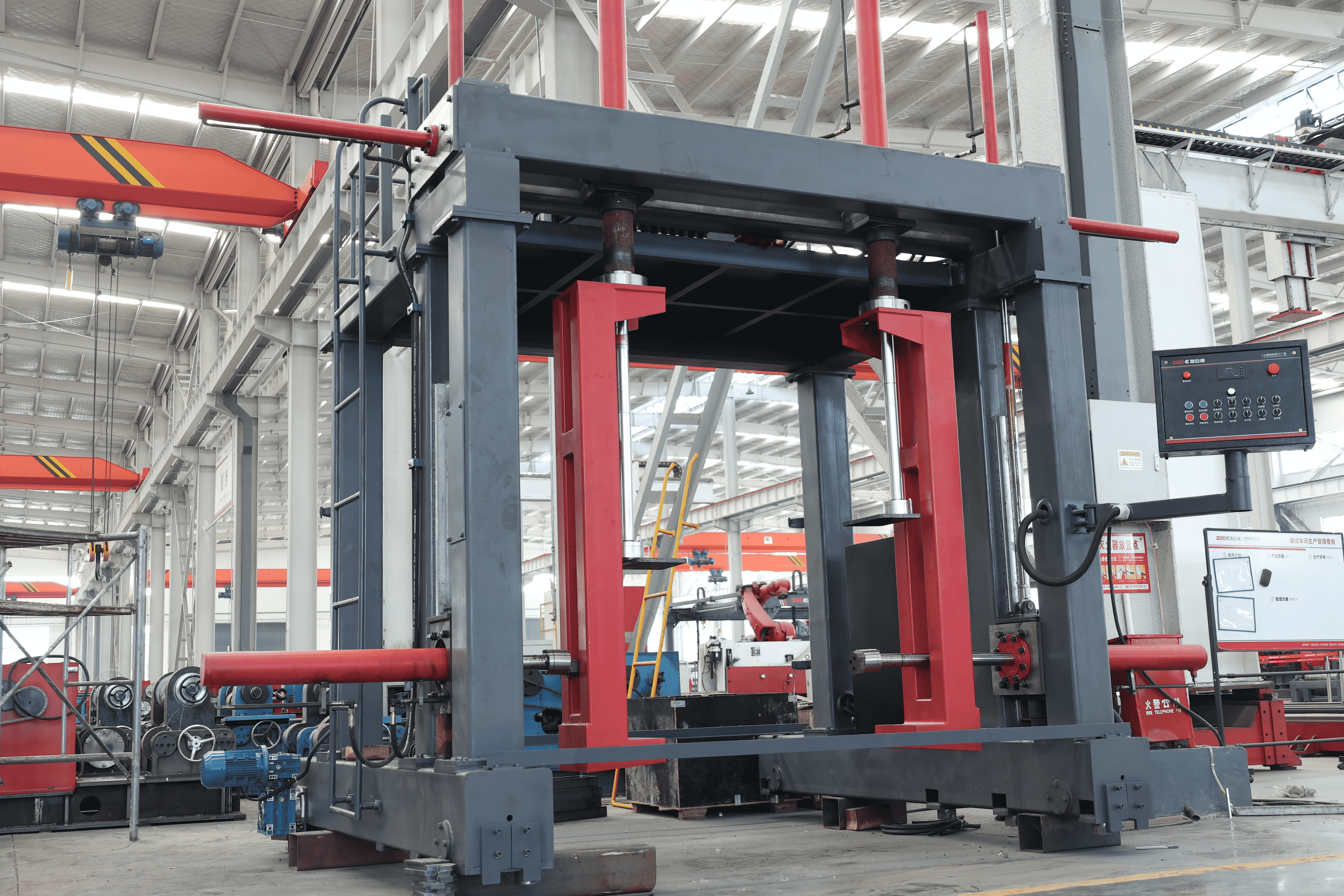
This machine is specialized equipment for assembling U-shaped and box-shaped beams. It mainly consists of a drive, frame, upper pressing device, side pressing device, hydraulic system, and electrical control system. The operation method is manual, using a stationary workpiece and a moving main machine for accurate positioning. The size of the applicable workpiece can be customized according to customer requirements.
Main Structure and Working Principle
Main Structure:
It mainly consists of a drive, frame, upper pressing device, side pressing device, hydraulic system, and electrical control system.
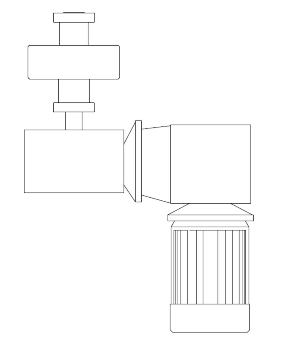
a. Drive: Symmetrically distributed, dual reduction motors drive wheels on the guide rail.
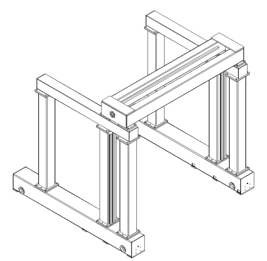
b. Frame: The frame is made of square tubes, integrating horizontal and vertical guide rails as the support for the upper and side pressing devices.
c. Upper Pressing Device: Hooks hold the workpiece, two large top cylinders press, and two small cylinders push the carriage to move the top cylinders laterally for positioning.
d. Side Pressing Device: The side pressing device uses one large top cylinder on each side of the workpiece to press, and one small cylinder to drag the carriage to position the side top cylinder vertically.
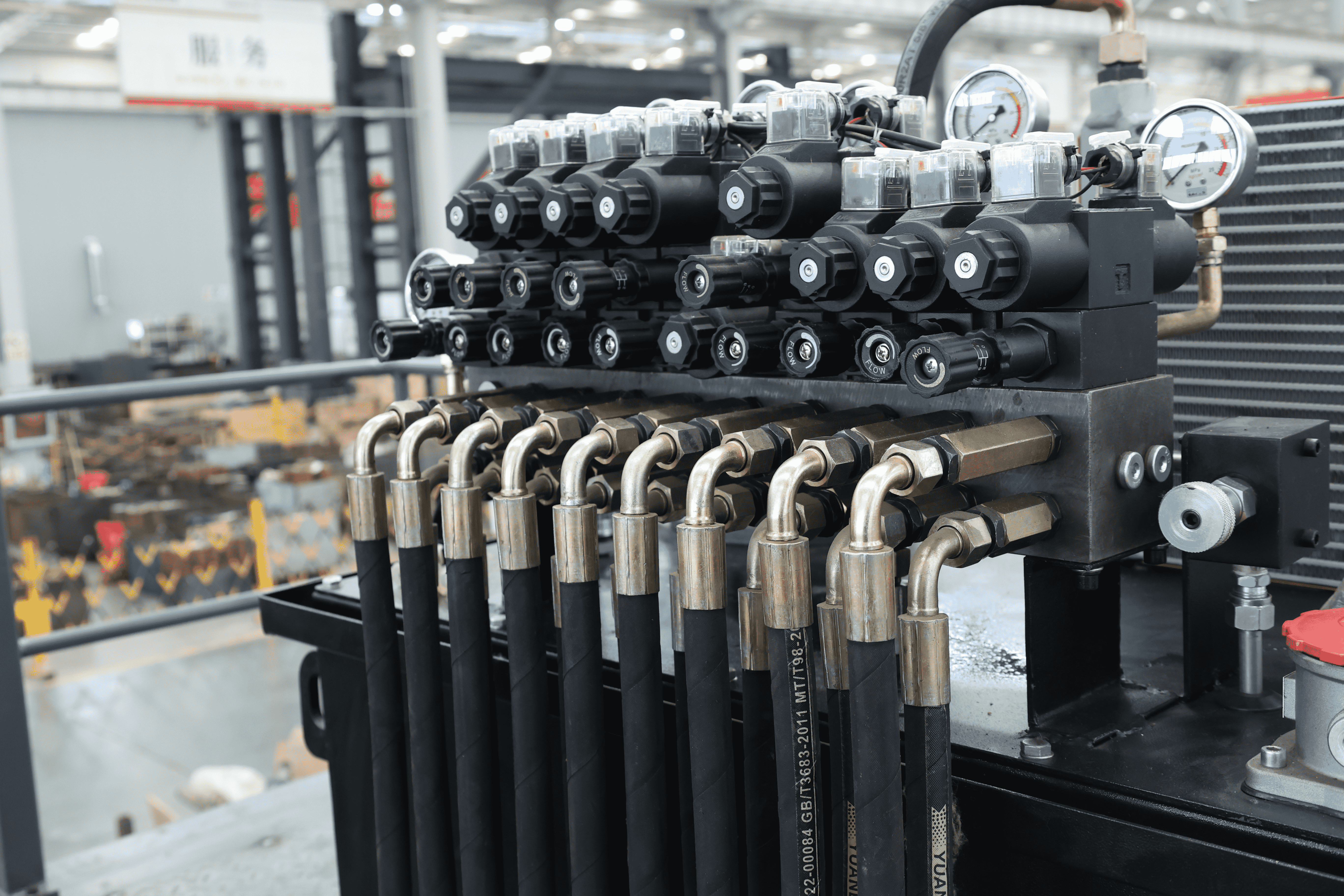
e. Hydraulic System: The hydraulic system consists of an oil tank, filter cooling, pipelines, and various control valves, using No. 46 anti-wear hydraulic oil with a working pressure of 16MPa. Maintenance methods follow standard hydraulic station procedures.
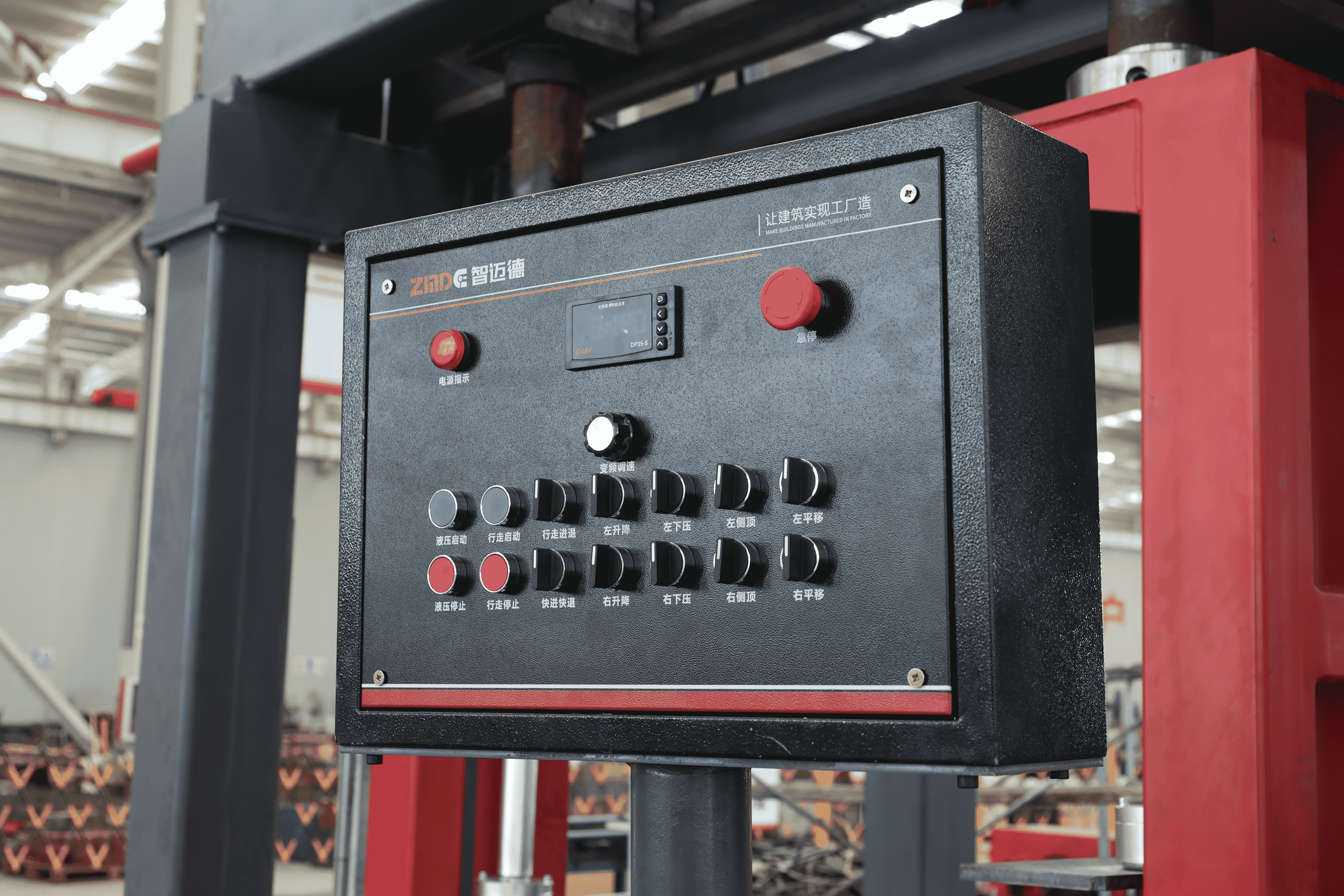
f. Electrical Control System: Uses PLC control to achieve various control functions.
Working Principle:
This machine uses a stationary workpiece and a moving main machine to clamp the workpiece in sections, and the clamped workpiece is manually spot-welded into shape. The characteristics of this machine are a compact structure, low equipment and usage costs, good quality, and high efficiency.
Main Performance Parameters
- Applicable Workpiece Size (mm): 300mm-1200mm
- Suitable Workpiece Thickness (mm): ≤80mm
- Maximum Load Capacity (t): 20t
- Frame Travel Speed (m/min): 4m/min
- Hydraulic System Pressure (MPa): 16MPa
- Maximum Pressure of Left and Right Cylinders (t): 15t
- Maximum Pressure of Upper Cylinder (t): 30t
- Machine Power (kw): 10kw
- Maximum Stroke of Left and Right Cylinders (mm): 800mm
- Maximum Stroke of Upper Cylinder (mm): 1000mm
- Up and Down Travel of Left and Right Press Heads (mm): 1000mm
- Upper Cylinder Beam Extension Stroke (mm): 820mm
Operating Instructions
1. The operator must be familiar with the structure and performance of the machine.
2. First, turn on all power sources and check whether each part is normal.
3. All cylinders must return to the initial position before working.
4. During work, follow the company's safety operation procedures to prevent accidents.
Equipment Maintenance
1. Clean the main machine and roller parts after daily work, and lubricate each guide rail surface before starting the main machine.
2. Lubricate the bearings and other transmission components of the conveyor roller with calcium-based grease every 15 working days; add N32 mechanical gear oil to the reducer and check once a month, replacing it every 6 months.
3. Add 46# anti-wear hydraulic oil to the hydraulic station, check once a month, and replace it every 12 months.
Scope of Supply
1. Main Machine Part: Main machine base, main drive system, left and right columns, bottom centering and pressing mechanism, lifting centering and pressing mechanism, upper platform, upper pressing mechanism.
2. Electrical Control System: Main electrical control box, control system, operating system.
3. Hydraulic System: Main hydraulic station, solenoid valve parts, pipeline system.
4. Hydraulic pipeline seals, copper sliders, and other easily worn parts are not covered by the warranty.
Appendix: U-Beam Assembly Machine Safety Technical Operating Procedures
1. Check for obstacles on the track before use.
2. When working, first close the circuit breaker in the power distribution cabinet, then close the circuit breakers in the control cabinet in sequence.
3. Turn on the oil pump, and its indicator light will be on.
4. Lift the first base plate onto the material rack, and weld the inner partition according to the process requirements. Lift the left side plate close to the base plate and inner partition, adjust the upper and side cylinders to the appropriate positions according to the U-shaped beam size.
5. Operate the left side pressing button to intermittently weld the side plate and base plate. Release the side cylinder, move the gantry a distance (distance according to process requirements), press the side cylinder again, and weld the side plate and base plate.
6. Weld the right side plate in the same way.
7. Lift the upper cover plate, press the upper and side cylinders, and weld the upper cover plate and side plates.
8. After intermittent welding, release the upper and side cylinders, move the gantry, and proceed to the next welding section.
9. After each shift, press the oil pump off button, turn off the control power, pull out the key switch, sequentially disconnect the circuit breakers in the control cabinet and the power distribution cabinet.
10. Clean up the site after work, maintain the cleanliness of the machine, and carefully fill out the equipment maintenance records.


