ZMD-Q1520-8 Roller Conveyor Shot Blasting Machine User Manual
Table of Contents
1. Purpose
2. Main Technical Parameters
3. Structure Principle, Adjustment, and Use
4. Lubrication
5. Foundation
6. Installation
7. Operation Procedures
8. Maintenance, Safety, and Troubleshooting

1. Purpose
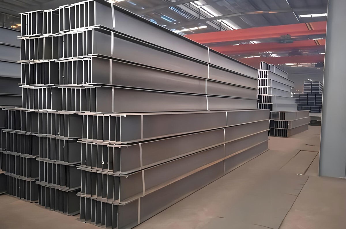
This machine is a multifunctional shot blasting equipment used for steel structures and various welded parts. It can perform powerful shot blasting on the surface of steel in its original state, removing rust, welding slag, and oxide scales to achieve a certain level of cleanliness and a uniform metallic luster. This process relieves stress, improves the quality of the surface coating, and enhances the corrosion resistance of steel structures and materials.
The machine is suitable for stress relief and surface rust removal in metal structure welding, steel products, railway vehicles, construction machinery, shipbuilding industry, and bridge manufacturing industry.
2. Main Technical Parameters
(1) Size
Width: 1500 mm
Height: 2000 mm
(2) Conveyor Roller
Working Speed: 0.5~4 m/min
Power: 4 kw × 2
Length: 12000 mm per side
(3) Shot Blasting Assembly (Eight Units)
Model: Q034
Shot Speed: 65~70 m/s
Power: 8 × 11 kw
(4) Elevator
Capacity: 120 T/h
Power: 7.5 kw
(5) Separator
Capacity: 120 T/h
Separation Zone Wind Speed: 4~5 m/s
(6) Screw Conveyor
Capacity: 120 T/h
Longitudinal Screw Conveyor Power: 5.5 kw
Horizontal Screw Conveyor Power: 4 kw
Separation Screw Conveyor Power: 4 kw
(7) Dust Removal System
Dust Collector:
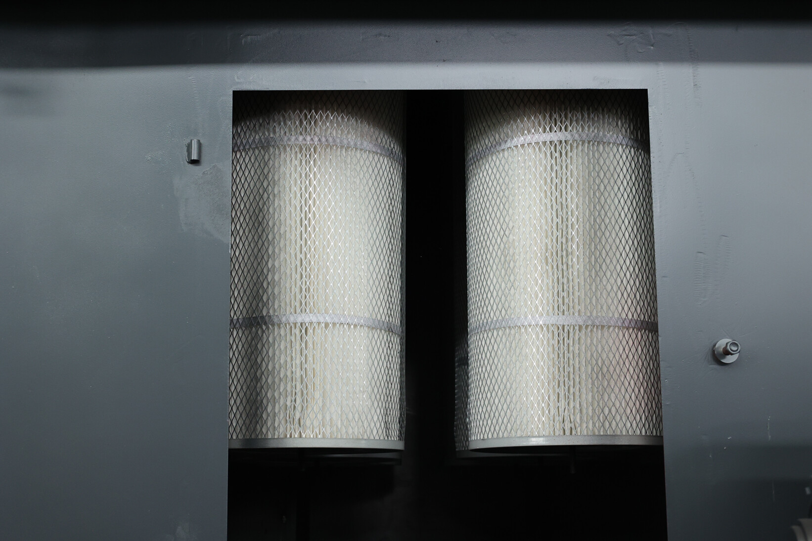
a. Model: Pulse Cartridge Dust Collector
b. Air Handling Capacity: 20000 m³/h
c. Dust Removal Efficiency: 99%
d. Number of Filter Cartridges: 12 pieces × 2
Centrifugal Fan:
a. Model: 4-72-8c
b. Wind Pressure: 2022 Pa
c. Power: 11 kw × 2
(8) Blowing Fan Power: 11 kw
(9) Total Machine Power: 150 kw

3. Structure Principle, Adjustment, and Use
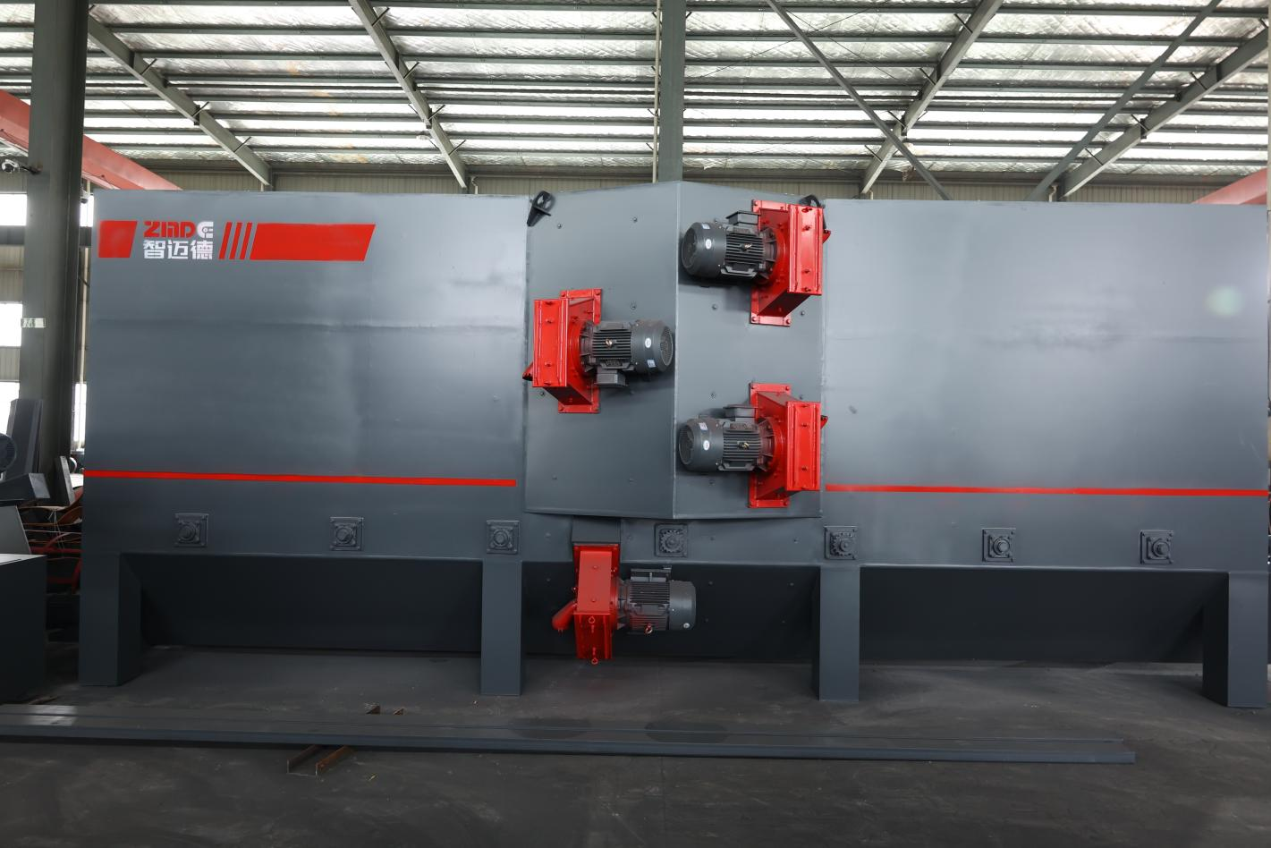
The machine is a roller conveyor high-performance shot blasting cleaning equipment. During the cleaning process, a speed-adjustable motor drives the conveyor rollers to send the workpiece into the blasting chamber. The workpiece surfaces are subjected to intense blasting from eight shot blasters from different spatial directions. The oxide scales and contaminants on the surfaces are quickly removed, and the surface obtains a certain level of roughness and brightness. The machine eliminates workpiece stress through intense impact, preventing deformation.
During the cleaning process, the mixture of shot and dust falls into the screw conveyor at the bottom of the chamber, which is then collected and lifted to the separator. Clean shots fall into the separator hopper, ready for reuse by the shot blasters. The dust-laden air is filtered by the dust removal system, achieving a dust removal efficiency of 99%.
This equipment consists of the following functional parts: main and auxiliary cleaning chambers, shot blaster assembly, conveying system, shot fall pipes, elevator, separator, shot conveying system, dust removal system, and electrical control system.
Cleaning Chambers
(1) Structure
The cleaning chambers are composed of a main and auxiliary chamber. These are large cavity structures, with the upper part box-shaped and the lower part conical. Cleaning operations are performed within this sealed cavity, consisting of front and back auxiliary chambers, the main chamber, rubber curtains, protective guards in the shot blasting chamber, and shot blasters.
A: The main chamber has eight shot blasters installed at the top, bottom, front, and back. The spatial arrangement has been tested and proven to achieve optimal cleaning of the workpieces.
B: The cleaning chamber is a multi-chamber assembly, with both the front and back being sealed. It includes multiple layers of rubber curtains to prevent shot leakage and maintains a slight negative pressure to prevent dust from escaping.
C: Wear-resistant guards are installed inside the main chamber to protect the chamber walls from wear, significantly extending the chamber's lifespan and utilizing the reflection of shots to continue effectively impacting the surface of the workpieces, thereby enhancing cleaning quality and efficiency.
D: The protective guards inside the shot blasting chamber are covered with wear-resistant nuts and are bolted on, protecting the bolt heads from damage and facilitating easy disassembly and replacement.
(2) Adjustment, Use, and Safety
A: The protective guards and cast nuts inside the shot blasting chamber are susceptible to wear and should be regularly checked for wear and replaced promptly. Care should be taken when installing the guards to ensure overlapping, preventing damage to the chamber walls and ensuring safety.
B: The rubber curtains inside the cleaning chamber are prone to wear and should be repaired or replaced promptly if damaged, to prevent the escape of shots and dust.
C: During operation, personnel should stay away from the chamber entrances and exits to prevent shot splatter into the eyes, and warning signs should be hung.
D: When entering the cleaning chamber for maintenance, the power must be disconnected in advance, warning signs hung, and powered operations are strictly forbidden as they could endanger personal safety.
Roller Conveyor and Conveying
(1) Structure
The workpiece conveying system consists of a roller conveyor powered by a cycloidal pinwheel reducer, which has a strong load capacity.
(2) Adjustment and Use
Adjust the speed of the conveying system from slow to high, gradually based on the cleaning effect on the workpieces, to achieve a high-quality cleaning effect and good economic performance.
Shot Blasters
(1) Structure
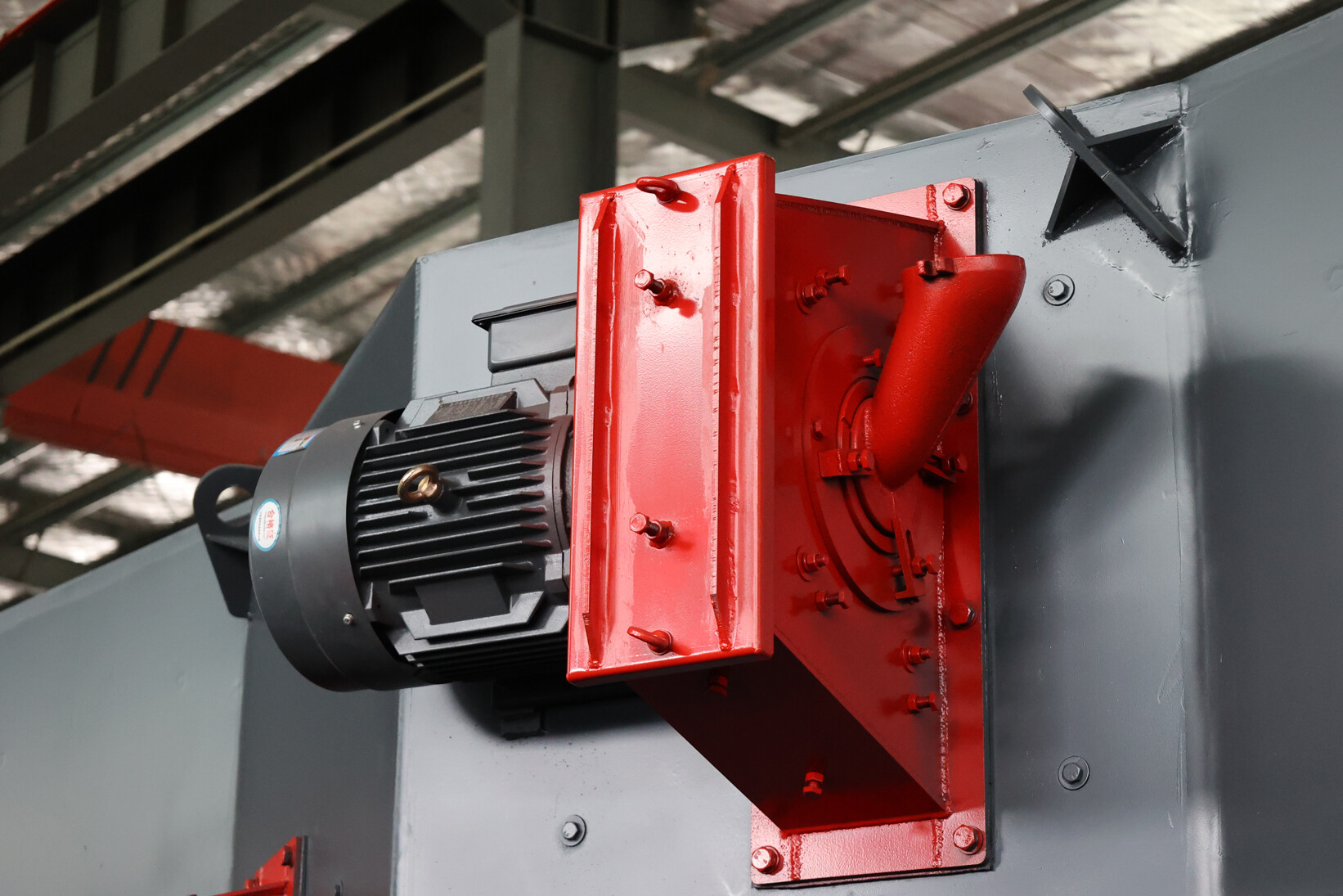
The shot blasters consist of an impeller, blades, a directional sleeve, and an inlet pipe. Shots are fed into the distributor wheel through the inlet pipe, pre-accelerated, and then ejected through the mouth of the directional sleeve, with the blades continuing to accelerate them to high speeds to forcefully impact the workpieces for cleaning.
(2) Adjustment and Use
A: To adjust the shot projection zone, first close the shot gate, place the workpiece in the projection area, stop the roller conveyor, ensure safety, then open the shot blaster, manually introduce a small number of shots into the shot pipe, and after the shot blaster stops, pull out the workpiece to check if the striking position is appropriate. Adjust the directional sleeve up or down as needed.
B: Uneven wear on the impeller can cause severe vibration in the high-speed running shot blaster. Check the condition of the blades before each shift and replace them if they show deep grooves or are worn more than half. Blades must be replaced in symmetrical pairs, and the weight difference between two blades should not exceed 5 grams.
C: Check the ammeter readings on the shot blaster; they should indicate the appropriate shot flow.
D: Do not open the shot blaster's cover while it is still moving or while the power is not completely disconnected.
Elevator
(1) Structure
The machine features a flat belt-driven bucket-type elevator, with the housing welded into shape, used to lift the mixture of shots and dust from the lower spiral conveyor to the top of the machine.
The elevator uses large pulleys to increase friction, with the lower wheel being cage-type to prevent sand, slipping, and misalignment, ensuring smooth and reliable belt operation and effectively extending the belt's lifespan.
If the belt in the elevator slips during operation, adjust the tensioning device or check for overload.
Separator
(1) Structure and Principle
The separator is a BE-type curtain structure. The shot-dust mixture is evenly fed into the separation area by the feed screw conveyor, forming a uniform curtain of shot-dust, which passes through a 4-5 m/s horizontal airflow for shot-dust separation. Shots and waste materials are separated based on their specific gravity, with clean shots falling into their respective channels; after passing through a grid, they enter a hopper for use by the shot blasters, while fine dust is drawn into the dust removal system, and the purified air is discharged into the atmosphere, capturing particulate dust.
(2) Adjustment and Use
A: Adjusting the gap of the separator's tongue plate can control the uniform distribution of the shot-dust curtain, achieving optimal separation effects.
B: The separator's outlet and the dust removal system's pipe connection have an airflow adjustment gate, which must be adjusted to an appropriate position to ensure that usable shots are not lost to the waste bin.
C: Qualified shots passing through the separator's screen effectively prevent larger objects from entering the hopper, ensuring the safe operation of the shot blaster.
Spiral Conveyor
(1) Structure
A spiral conveyor and shot fall chute are located under the cleaning chamber to collect the mixture of shots and dust, which is then sent to the elevator and on to the separator. They consist of a cycloidal pinwheel reducer, spiral shaft, housing, and bearing seat.
(2) Adjustment and Use
A: After installation, the spiral conveyor shaft should rotate flexibly without any jamming.
B: Excessive shots in the spiral conveyor trough can increase the starting torque, leading to equipment failures. Issues should be promptly resolved, and large quantities of shots should not be added to the collection hopper at once but rather introduced slowly.
Shot Conveying Pipes
The shot conveying pipes have a dual function, each gate tube is equipped with a gate plate for adjusting the flow of shots and facilitating maintenance. The opening and closing are controlled by an electromagnetic valve below.
Dust Removal System
The dust removal system mainly consists of dust removal pipes, a pulse cartridge dust collector, fans, and air ducts. The dust removal efficiency of this system is 99%, achieving high dust removal performance. The air containing dust can be directly discharged into the atmosphere after dust removal, without the need for purification equipment. This complies with the "Comprehensive Standards for the Control of Air Pollution" (GB16297-1996) and the "Industrial Standards for the Emission of Waste" (GBJ14-93).

4. Lubrication
New equipment needs to be lubricated according to the requirements before use.
5. Foundation
The foundation diagram provided by our company only offers the installation position, embedded parts, and pit dimensions for user reference. Users must design the civil engineering based on local water level geological data and machine weight.
6. Installation
The machine is divided into groups for transportation convenience. During on-site installation, reshaping should be done as per the situation.
7. Operation Procedures
Pre-Shift Equipment Check
(1) Check the wear condition of the protective plate and door curtain of the shot blasting chamber. Report any issues and replace them promptly.
(2) Ensure no one is inside or near the inlets and outlets before starting the machine.
(3) Follow the electrical operation instructions during the process.
8. Maintenance, Safety, and Troubleshooting
Maintenance and Care
A. The machine should be regularly inspected, maintained, and lubricated.
B. Do not leave tools, screws, or other debris inside the machine during maintenance.
C. Ensure the pit is dry to prevent rusting and clumping of the shot material. If the machine is unused for a long time, run it for half an hour periodically.
D. Regularly remove waste from the separator and dust collector to ensure normal operation.
Pre- and Post-Operation Checks
A. Check the wear condition of protective plates, rubber curtains, and other vulnerable parts before operation, and replace them promptly.
B. Check the fit of all moving parts and tighten any loose bolts promptly.
C. Remove any debris inside the machine to prevent blockages, and check that all lubrication points meet the standards.
D. Ensure no one is inside or near the inlets and outlets before starting the machine.
E. Follow the electrical operation procedures correctly.
Operation Checks
A. Regularly check the cleaning quality of the workpieces during operation and adjust the shot blasting angle and conveyor speed as needed.
B. Monitor the workpieces to ensure they are not misaligned and adjust them promptly.
C. Pay attention to the vibrations and sounds of the shot blasters, as well as the temperature rise of bearings and motors. Stop the machine for inspection and replace the blades if any abnormalities are found.
Safety
A. Only qualified personnel are allowed to operate and maintain the machine.
B. Disconnect the power supply and hang warning signs in visible locations during maintenance.
C. Avoid open flames near rubber curtains and dust collectors.
D. Ensure protective covers are securely installed during machine operation.
E. Disconnect the main power supply in case of a power outage.


